Second "Try"
79
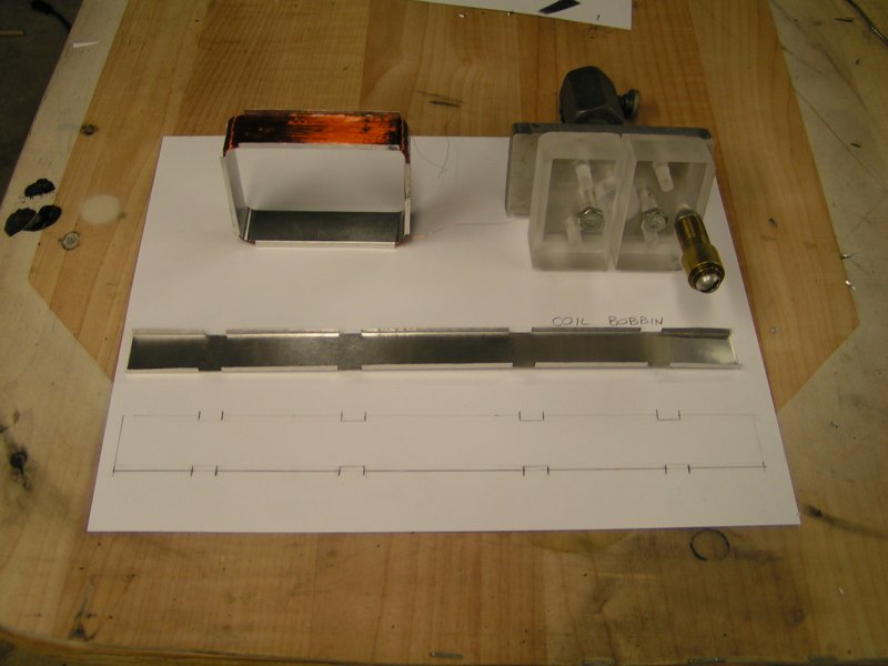
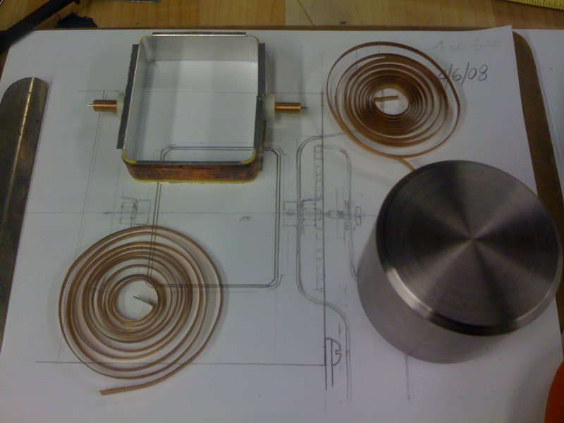
First wound coil at upper left, coil winding form at right,
and strip of soft temper aluminum laid out ready to be shaped
around winding form for a second attempt.
06-APR-2008
80
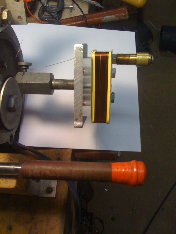
View of finished coil. To alleviate potential for the bobbin chafing
the magnet wire, identical rubber bands were placed at each edge.
As the coil was wound slowly around a "zillion" times to achieve
a measured resistance of 600 ohms, it was coated with 2-part epoxy.
Attaching Pivots
81
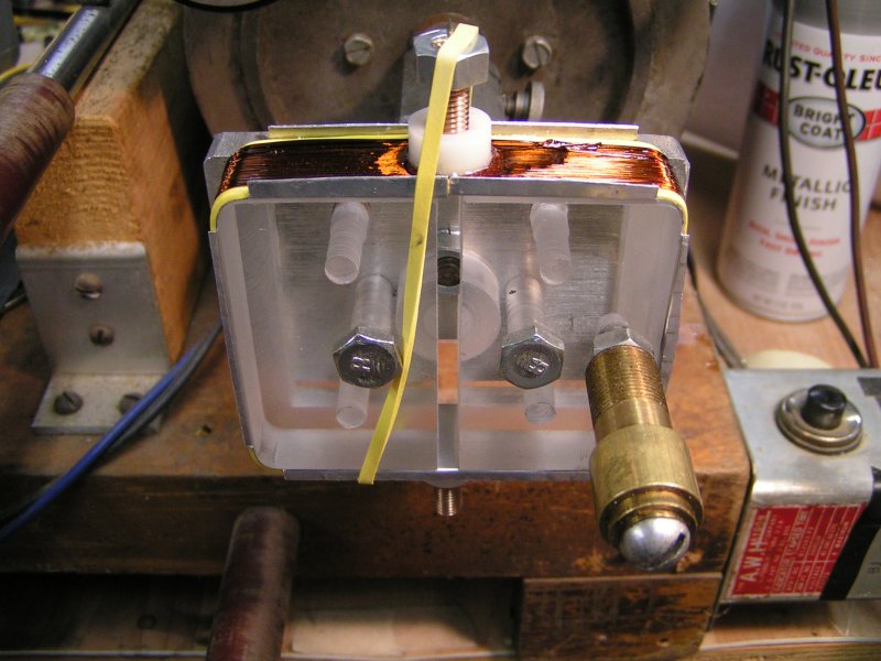
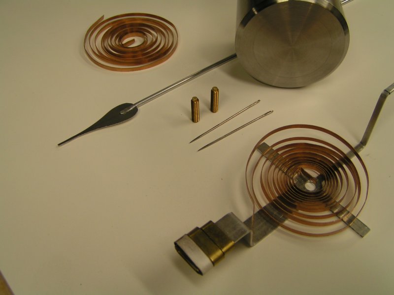
Each pivot point is a stainless steel sewing needle cut to required length.
The needles were pressed into a drilled hole on the end of threaded 1/4-20
bronze material which was threaded into the white plastic component glued
to the coil assembly. The entire group of glued parts were allowed to fully
cure before being removed from the coil form.
17-MAR-2008
82
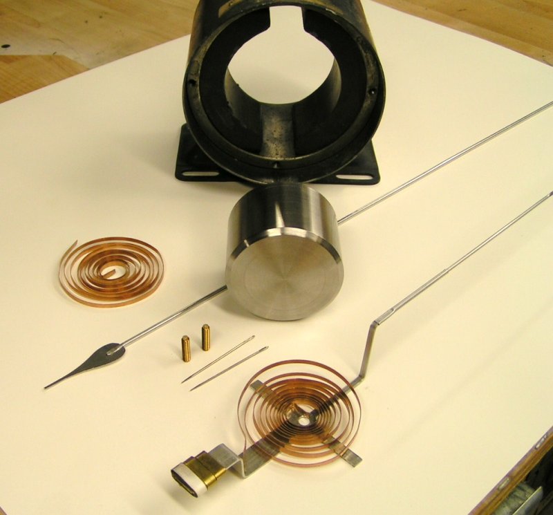
The indicating needle in the foreground is from the original meter movement I built
in 2002. The two threaded parts standing upright are the sapphire jewel bearing assemblies.
09-APR-2008
84
Parts for the meter movement nearly ready for assembling into a working apparatus.