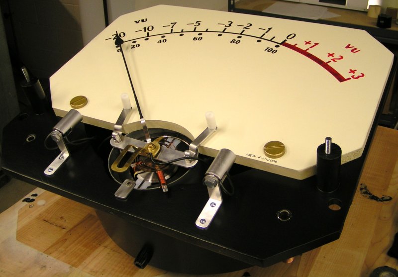
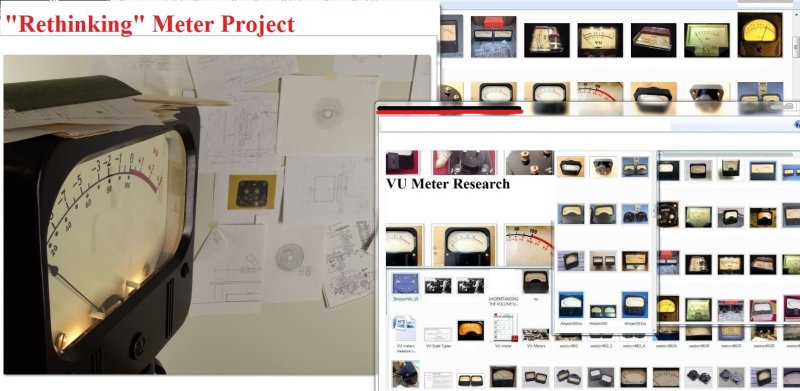
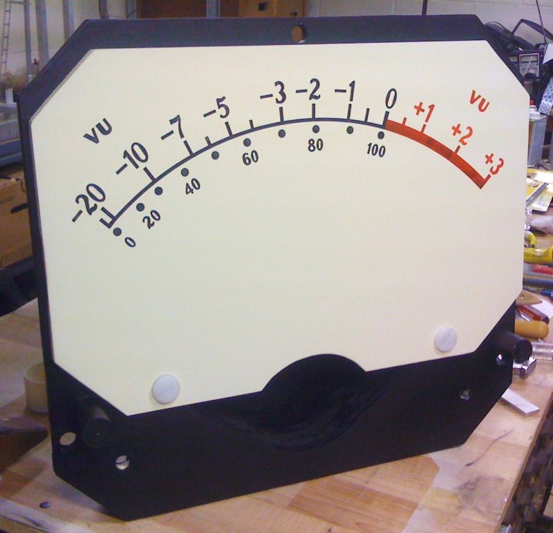
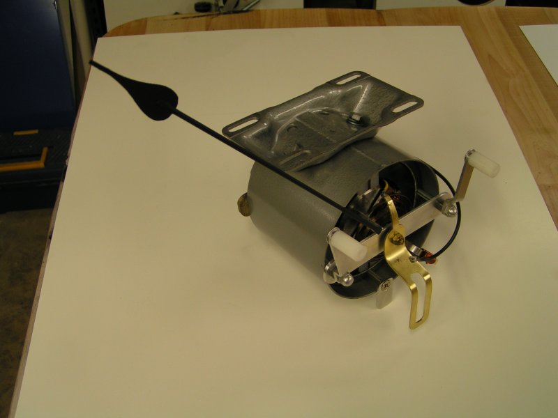
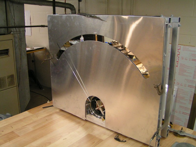
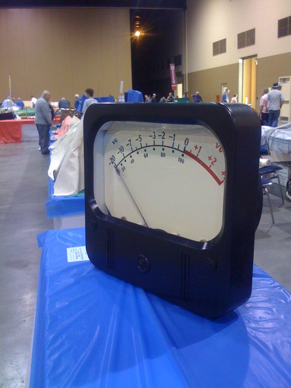
VU Meter
Meter resting on workbench. Two candelabra base lamp sockets shown mounted to "L" brackets provide
the option of lighting the meter face with either a standard 120 volt low wattage lamp, an LED,
or a lower voltage bulb depending on available power sources. (No lamps installed in this photo.)
Prototype Constructions
2
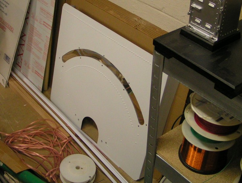
This is actually the first Meter Face I built in 2002. It sat collecting dust for several years.
The material used for the mirror on the face was acrylic plastic which began warping after a while.
In "rethinking" about the whole project, I decided to start building a new frame having more
rigidity to hold an actual glass mirror. The idea of making the meter a VU type meter hadn't
occurred to me yet. At this point, I'm thinking the end result will be some type of multimeter.
Prototype Constructions
3
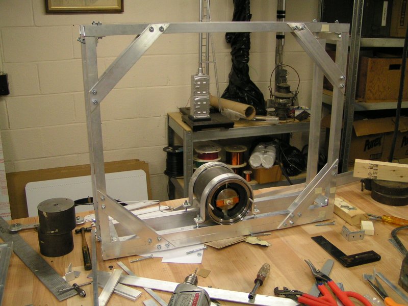
Here, an aluminum frame is starting to take shape. I was also getting reacquainted with where I had
left off with the project in 2002. The permanent magnet assembly adapted from a NEMA 56 Frame
electric motor had been dismantled. Parts, and pieces I had constructed earlier were missing or lost.
Prototype Constructions
4
Aluminum meter face with glass mirror.
Prototype Constructions
5
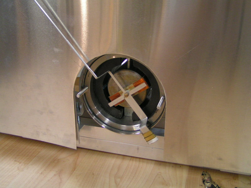
In this shot, you can see where rust was starting to form on the [iron] center piece because of the
project sitting idle for nearly 5 years. I was also thinking about how I wanted to make the device a
more "respectable" display (in my mind), and what I was seeing unfold here was just not working.
Re-Thinking
6
As a model maker, "you" typically scale down subject matter. Creative thinking exposed its delight
for me one day when it seemed obvious to make the meter a working model of some "real thing". I had
a past working in broadcasting, and the concept of turning the project into an actual working VU Meter
started to take [Form]. The next decision would be what style, and what previously manufactured product
would make sense to copy. Vintage, "Retro", and the Weston Electrical Instrument Company all came to mind.
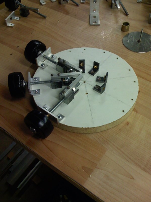
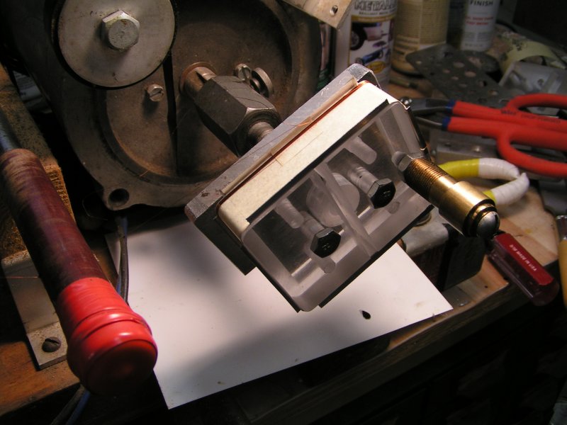
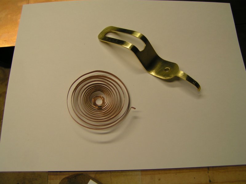
Spring Fixture
7
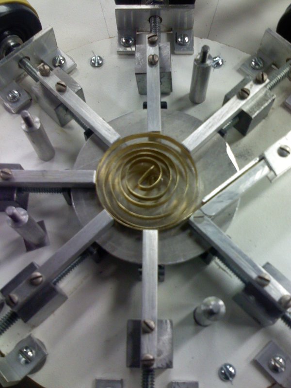
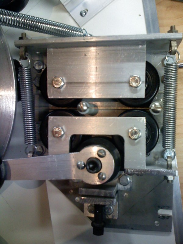
Constructing Spiral Spring Fixture
10
Material is fed, or pushed into the confines of the retracting fingers.
A clear acrylic cover (not shown in this photo) retains the material
from popping out while being wound.
14-NOV-2007
12
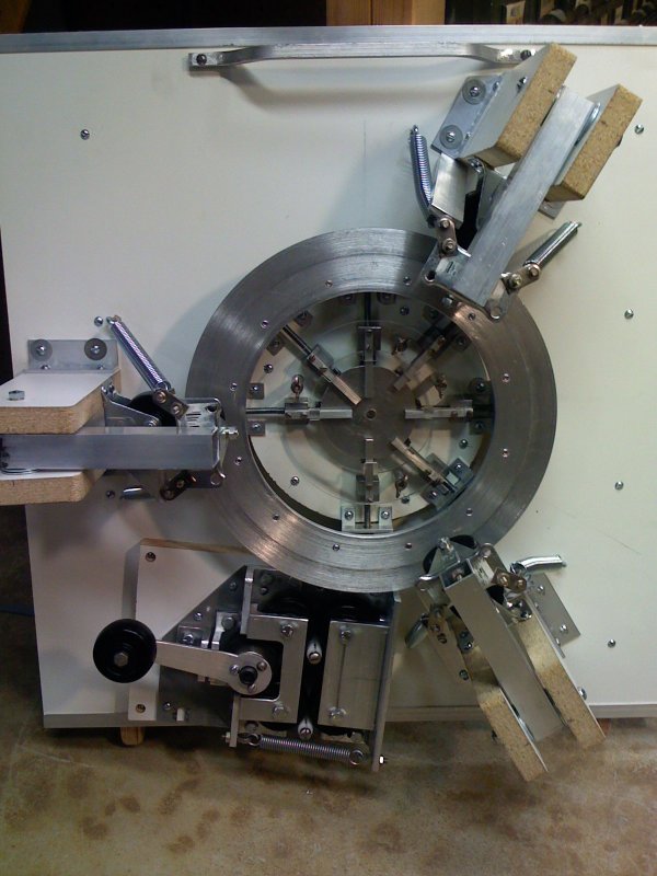
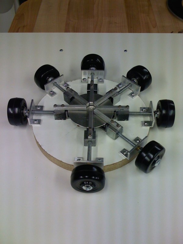
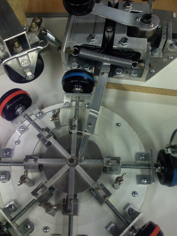
A contraption of a project within a project.
A completed fixture for winding "spring tempered"
phosphor bronze material into a spiral spring.
03-FEB-2008
13
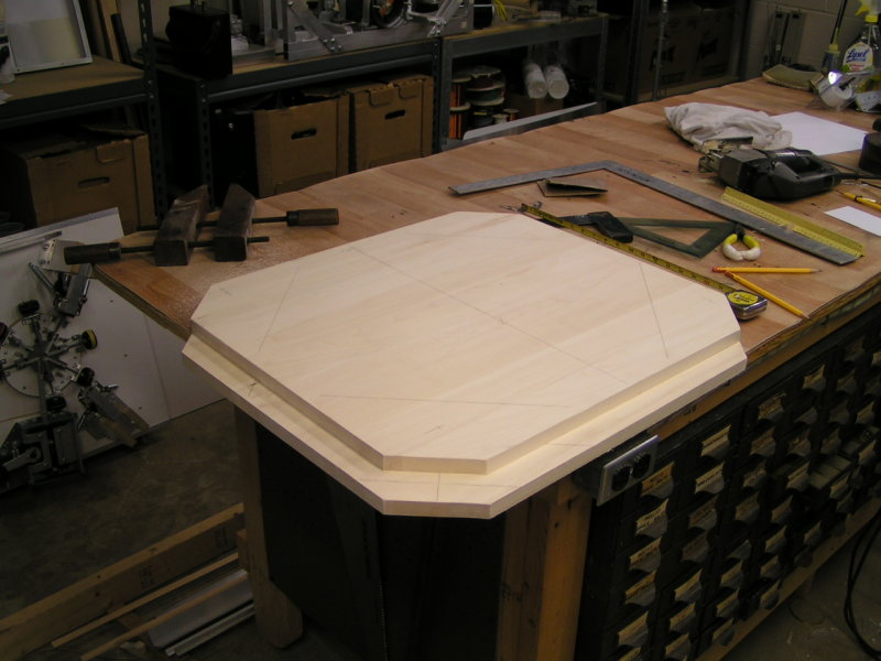
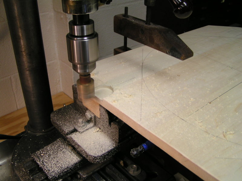
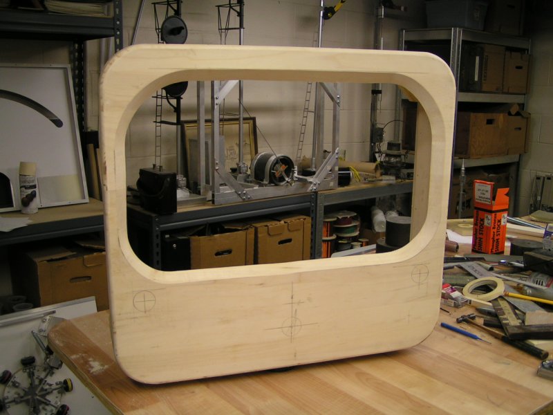
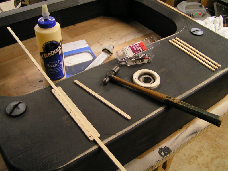
Getting [Started] with cutting wood Meter Housing material.
04-FEB-2008
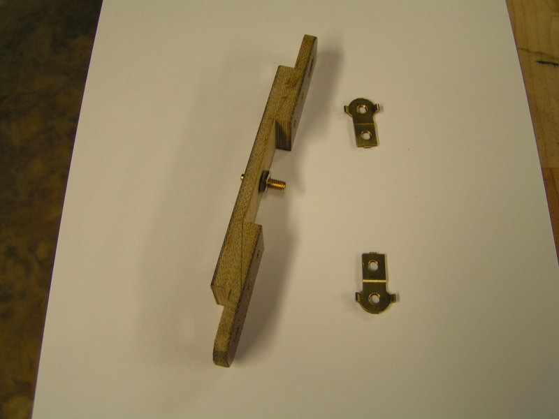
15
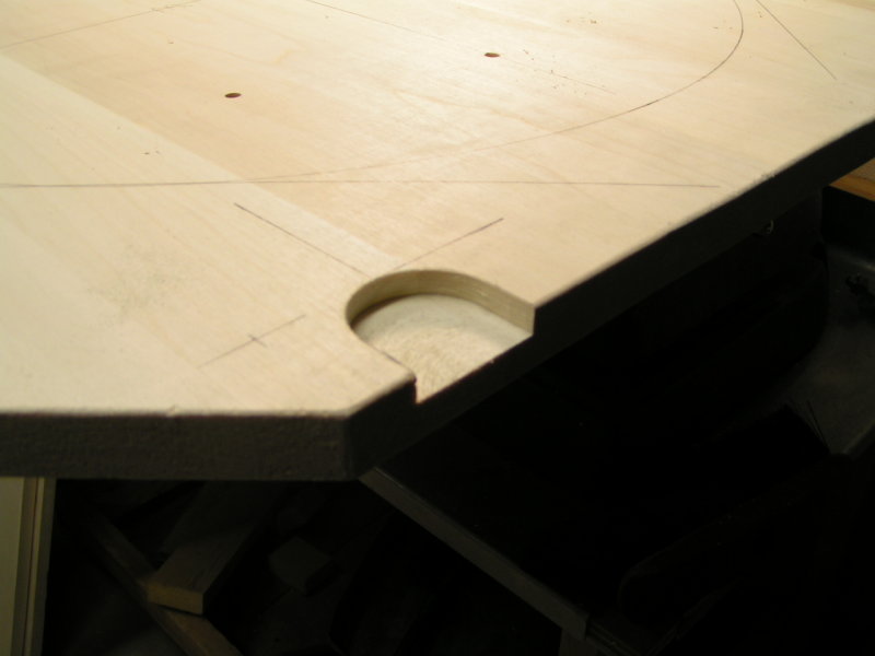
Notch for recessed head of back mounting screw.
04-FEB-2008
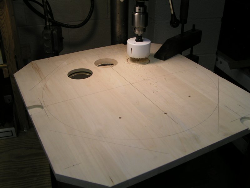
16
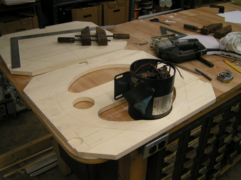
The bulk of the wood cutting was by "guided hand" using
a sabre saw. So it was important to have all radius turns
located uniformly. Hence, cutting out located circles first.
Two (2) Meters
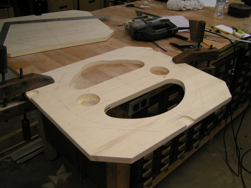
17
At this stage of the project, I was still building two meters for "Stereo".
Further into construction I abandoned making identical parts due to time
constraints. Procrastination, and Deadlines did me [in]. I had to focus
on getting one unit finished if I was going to have a completed meter
available in time for it to be displayed in April at the N.A.M.E.S show.
04-FEB-2008
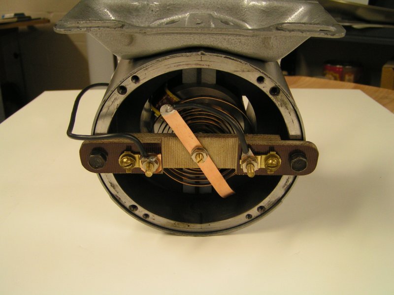
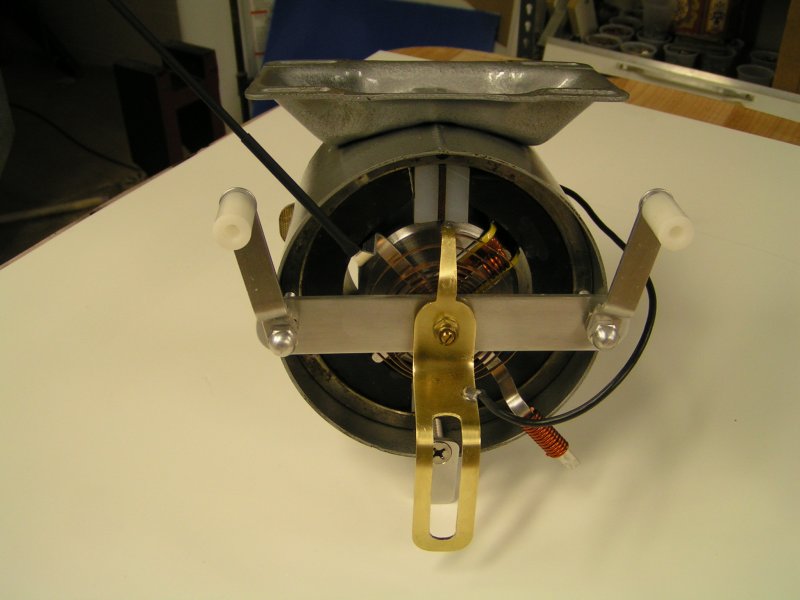
18
Checking the NEMA 56 frame clearance and proper fit.
05-FEB-2008
19
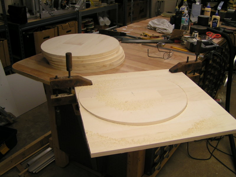
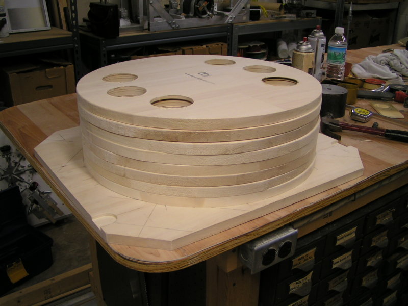
Cutting out wood lamination's for back body of meter housing.
21
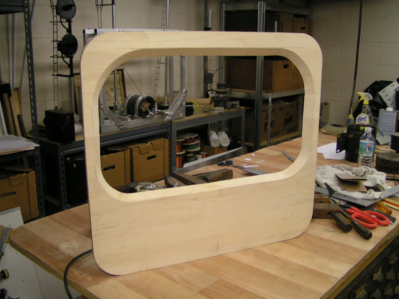
Cutting out meter face window.
09-FEB-2008
23
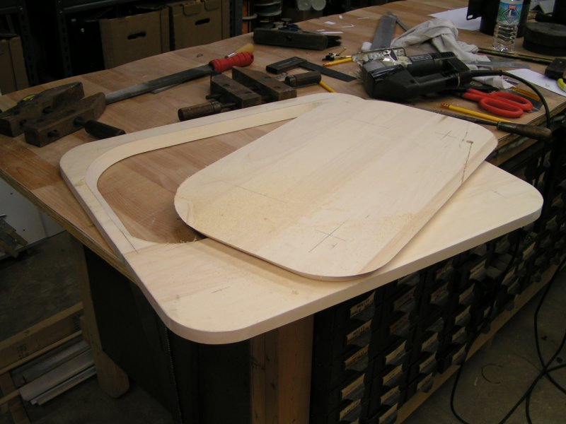
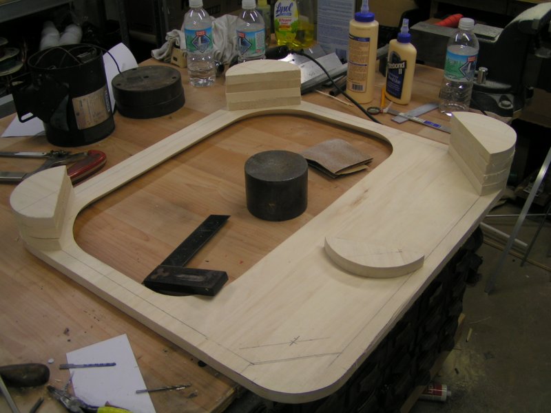
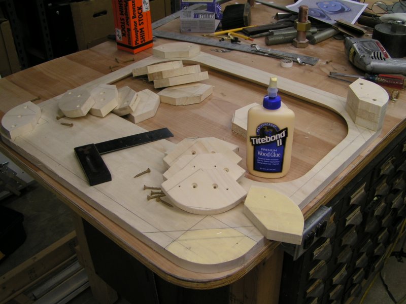
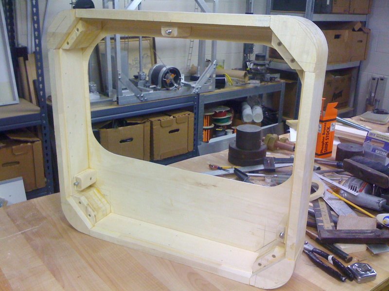
Cutting, and laying out front housing corner pieces.
15-FEB-2008
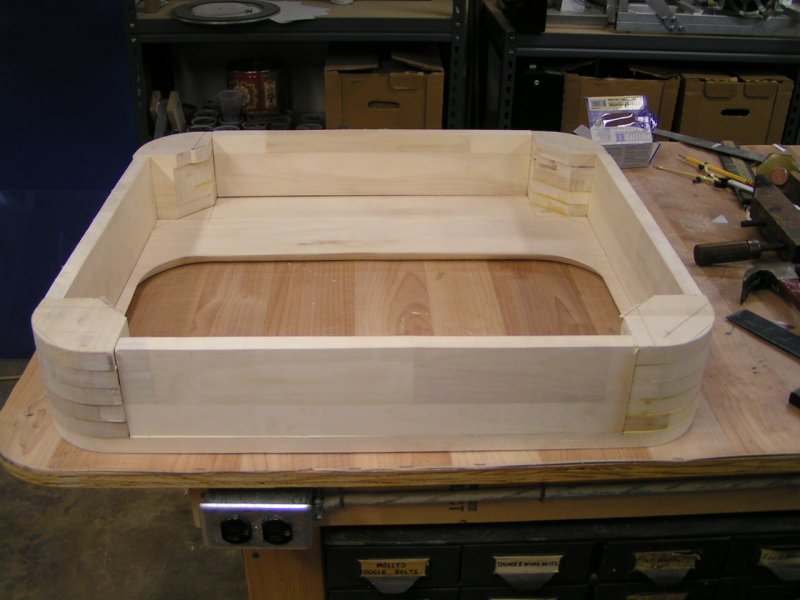
24
Gluing, and screw-fastening corner pieces.
15-FEB-2008
25
Getting a "visual" on selecting connection stud material in relation to the meter housing scale/size.
20-FEB-2008
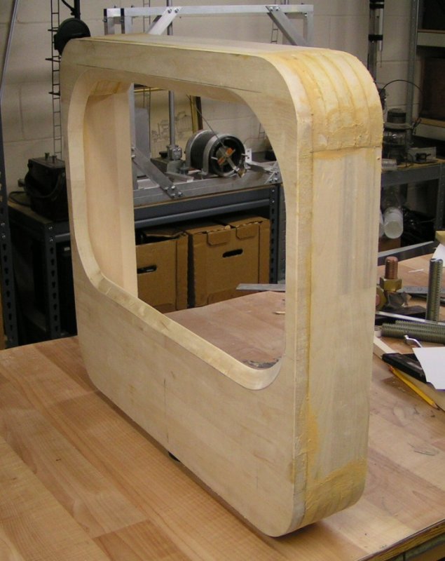
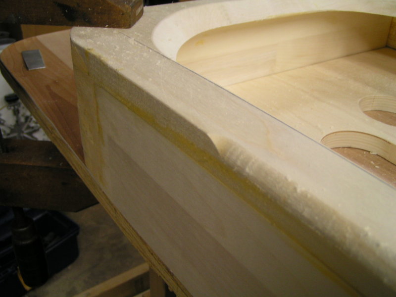
28
Rounding, or chamfering front edge of meter housing.
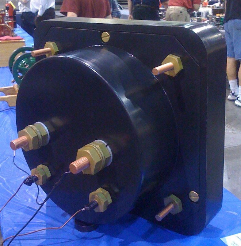
Connection Studs
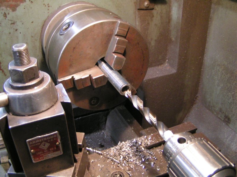
31
The main connection terminal studs are made from 1-1/8 -7 threaded material. All of the
mounting studs, and meter connection studs were drilled out to reduce material weight.
(3/4-10 threaded rod shown here)
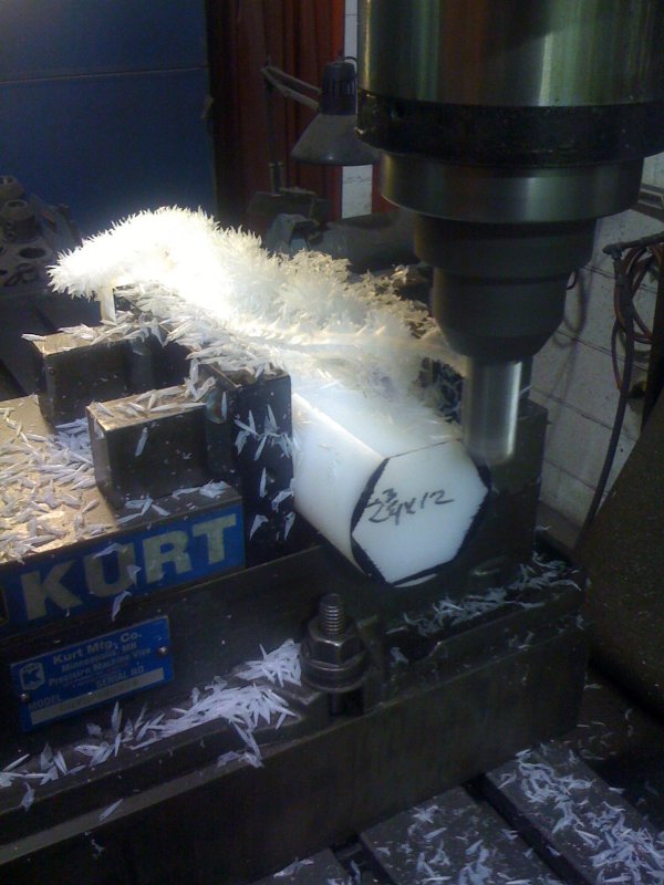
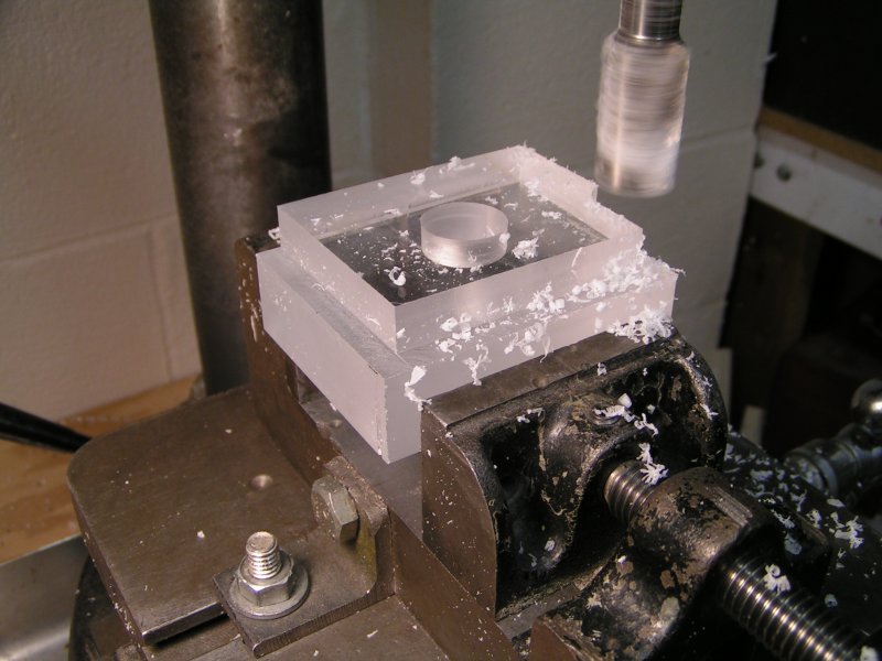
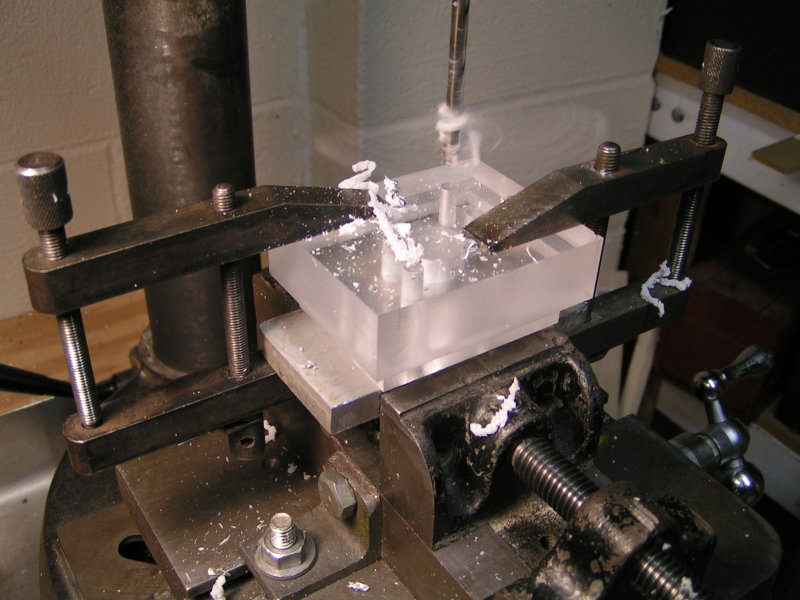
Milling Nuts
32
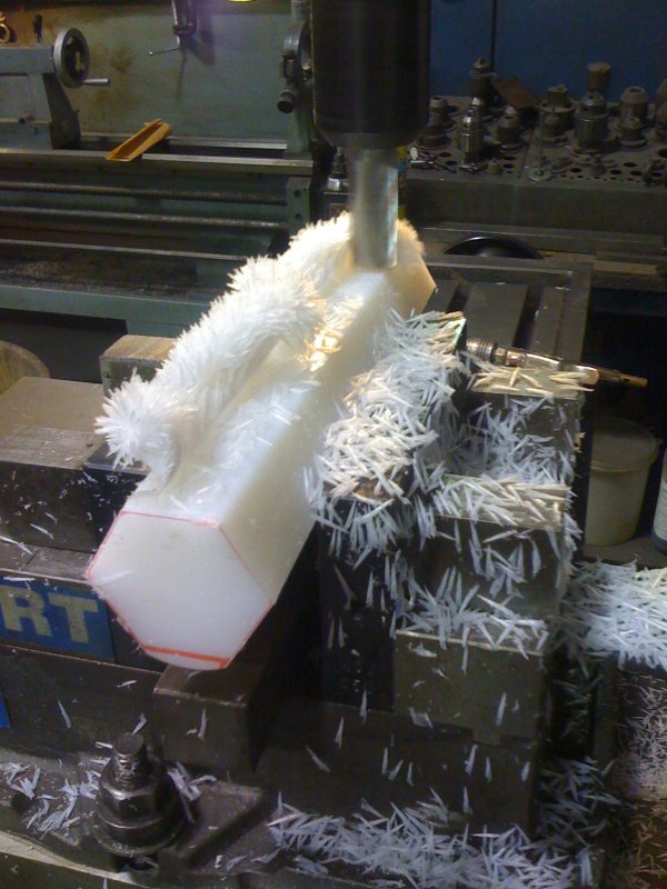
As with the connection studs, the terminal and mounting nuts had to be light in weight.
This photo shows a piece of UHMW Polyethylene stock being milled into the required hex nut shape.
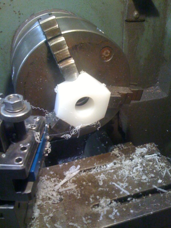
34
The UHMW stock was sliced creating individual hardware nuts which were then faced off
in a lathe on each side as shown here. The center hole is tap threaded to fit respective studs.
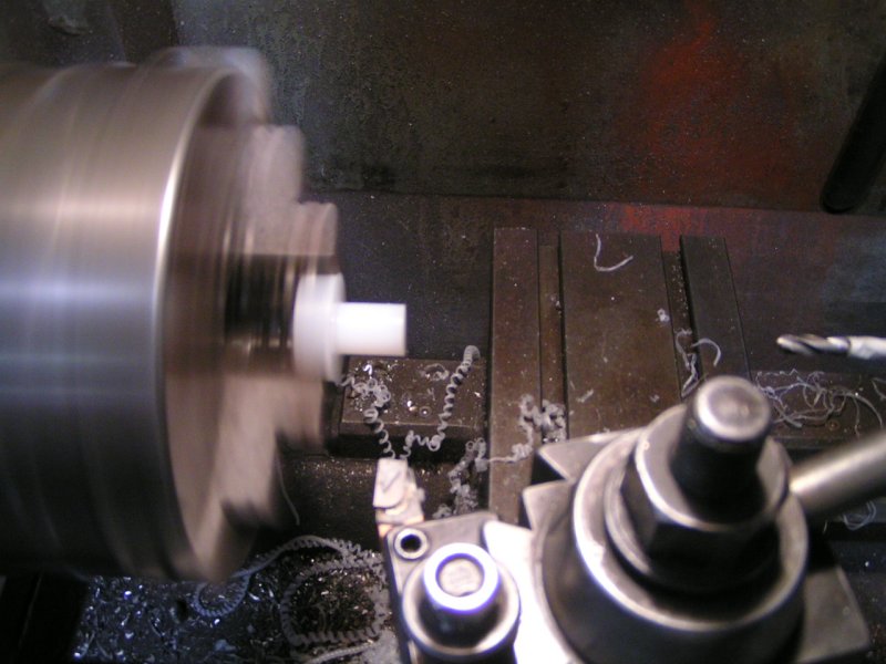
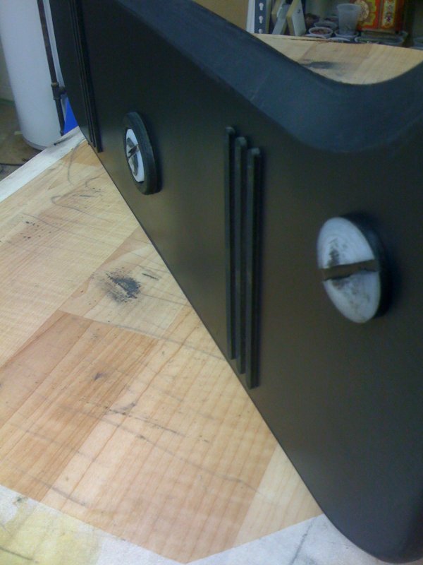
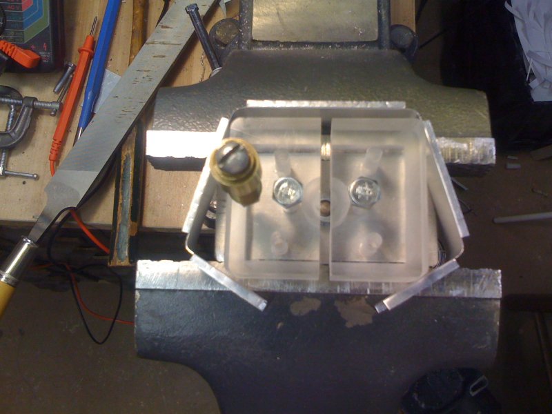
Turning Screws
35
There are three mounting screws visible on the back of the meter housing,
and two visible mounting screws securing the meter face inside the housing.
These items were also made from (plastic) to keep weight reduced.
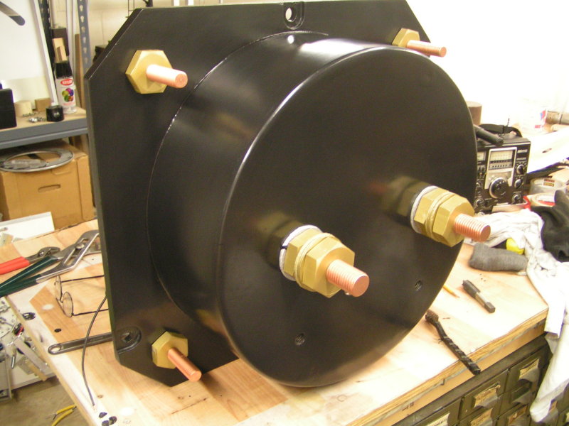
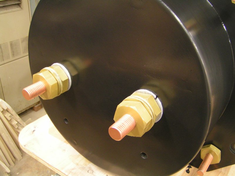
Stud and Nut
36
Getting an idea of how the connection studs and nuts will appear with "copper"
color and "brass" color paint applied to simulated actual hardware fasteners.
23-FEB-2008
37
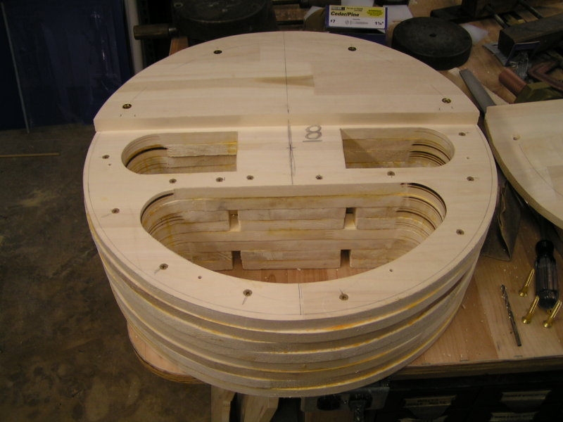
Wood lamination's stacked for checking clearance fits, etc.
Gluing Lamination's
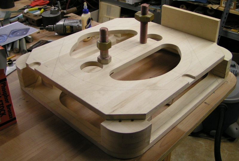
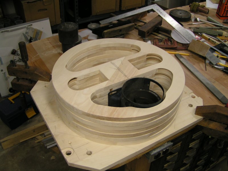
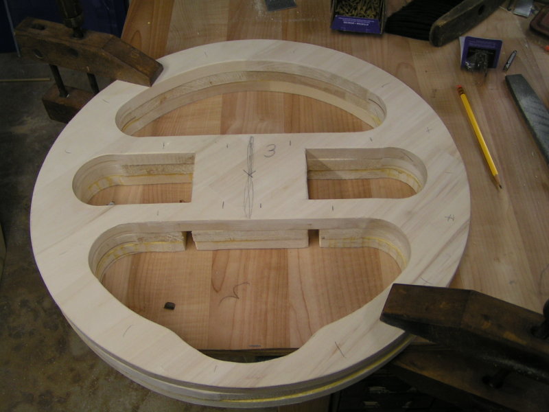
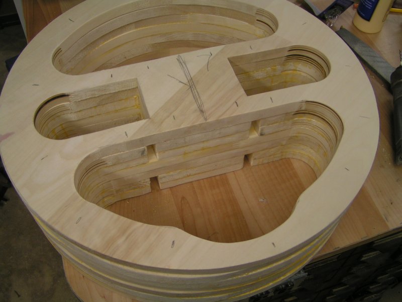
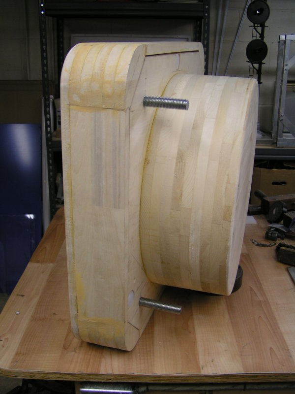
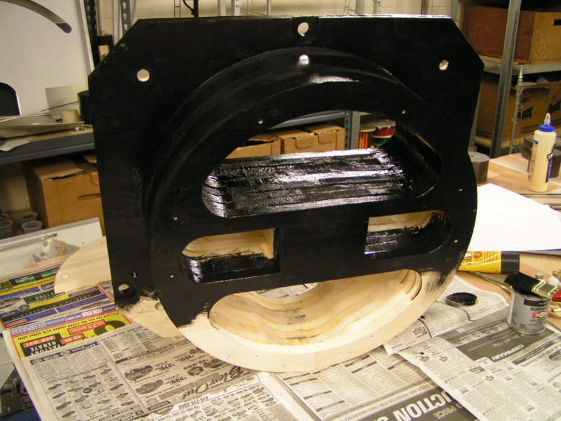
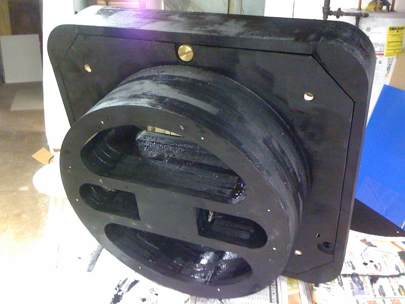
39
Each wood lamination was glued, and screwed in place one after the other.
The slots were strategically placed for mounting the NEMA 56 motor frame.
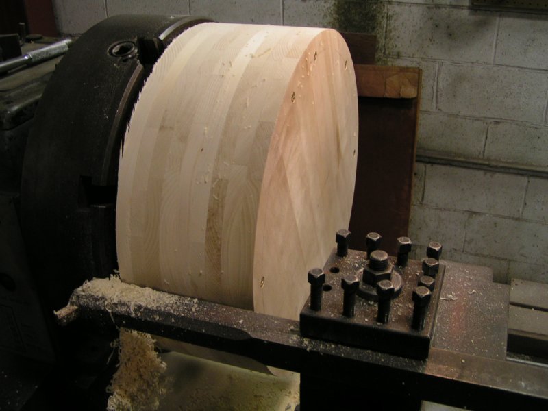
The voids created by cutting out material were purposely done for reducing the
overall weight, and for providing a means for "chucking" the assembly onto
a lathe for turning the outside diameter smooth.
24-FEB-2008
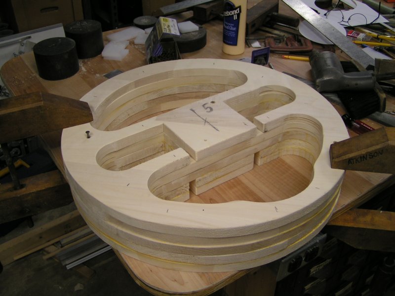
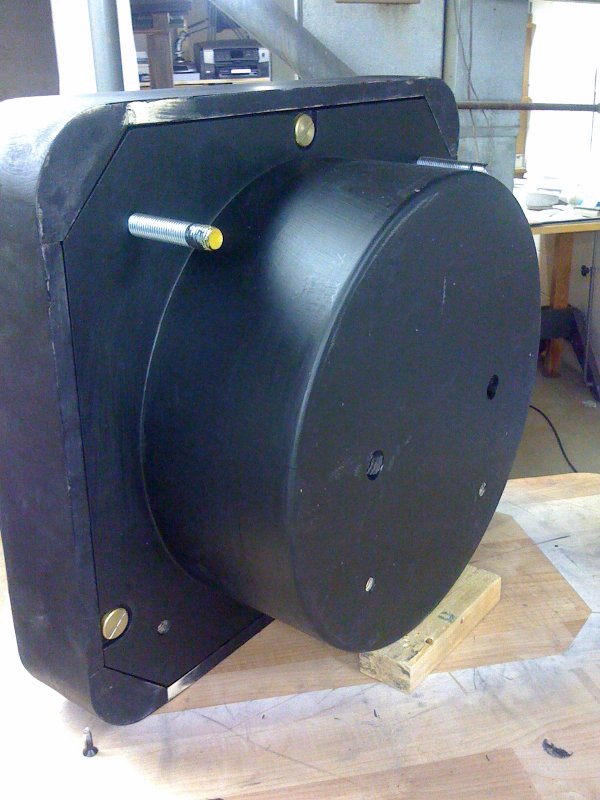
41
The last lamination panel was made removable to allow access
in mounting the NEMA 56 frame at a later point in the project.
24-FEB-2008
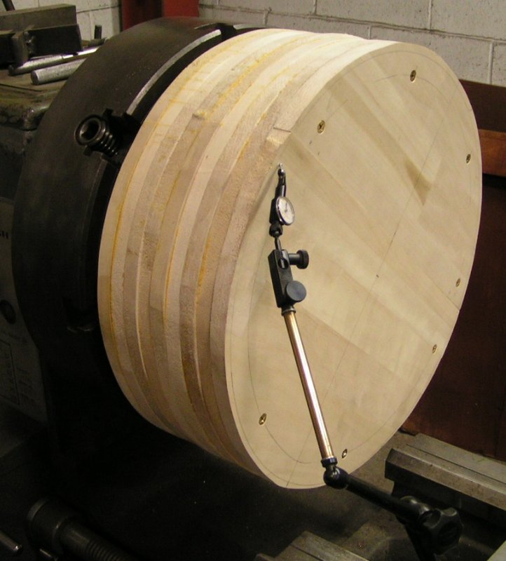
43
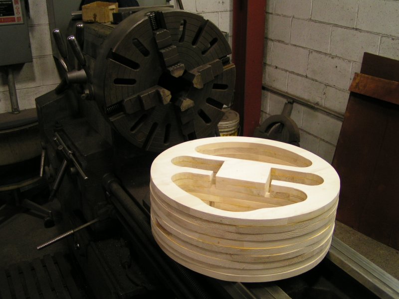
The laminated wood assembly is clamped into (or onto) a four-jaw lathe chuck,
and carefully indicated [IN] for as little "run-out" as possible.
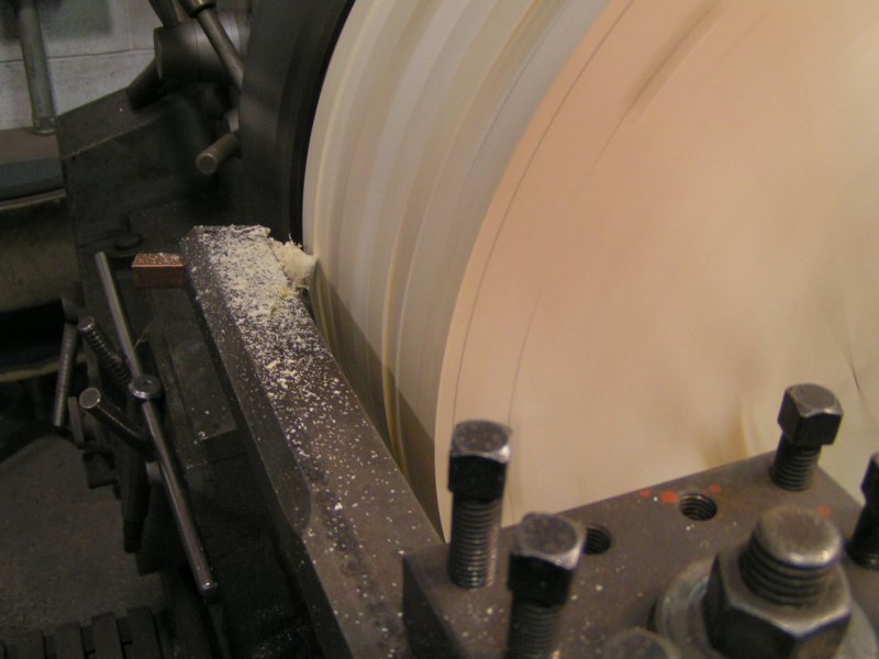
TURNING
45
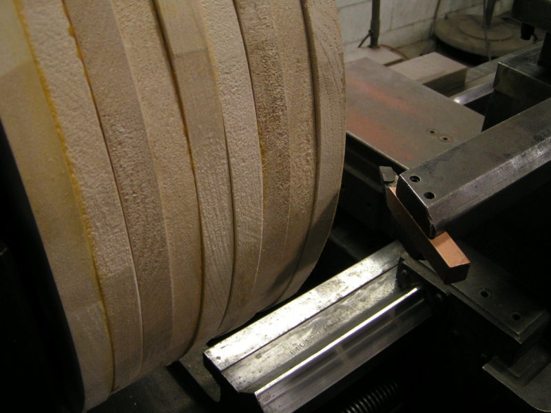
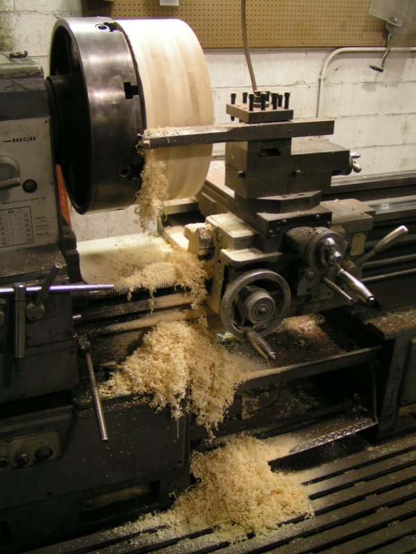
Scribed pencil line at far edge of the assembly
marks where (when) to stop removing material.
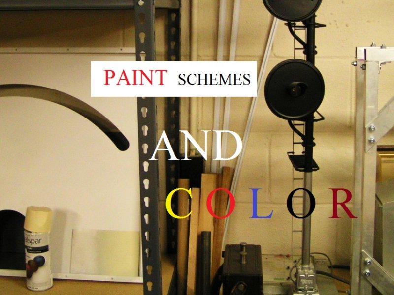
Meter Face Color
49
In building a model of anything, it's easy to get "sidetracked" into exploring the purpose of,
or the reason why something was designed, and made the way it [IS]. Understanding the history
of the standard established for the (volume unit) by Bell Laboratories, and the various broadcasting
companies during the late 1930s, it was not difficult to read and learn about this using the Internet.
Here's what I could not find.
I could not locate information anywhere related to the color of the VU Meter face.
I'm building a model. I need to know this stuff. ............................................................
Any radio station I was employed with always had audio mixing boards with meter faces having
a certain color. Tape recorders and other types of audio equipment utilized a similar color with
their meter faces as well. ...........................................................................................
Was it tan, beige, almond, antique white, moccasin, light yellow? The list of colors could go on.
Where did the meter Manufacturer's choice in color originate? And what color is it?
.......................................................................................
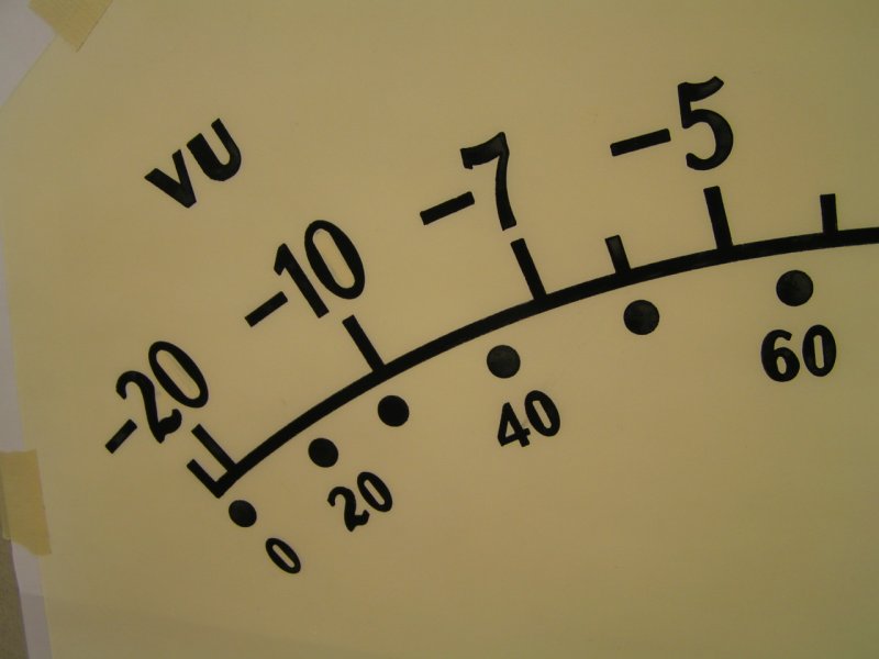
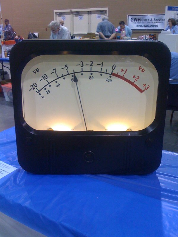
November 29, 2010 UPDATE: Two conferences held in June, 1938 at the Institute of Radio Engineers annual
convention in New York established the design of the volume indicator. In addition to the meter's electrical specifications, other characteristics were chosen to
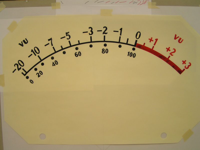
make the instrument readable over long periods with little eyestrain or fatigue. The meter face referred to as a "Scale Card" was designated Cream Yellow with
markings in Black and Red. (Gracious Thank You to Jack Orman for providing documentation from 1939 "Electronics" reprint, McGraw-Hill Publishing Co., Inc.)
Learning About FONTS
50
At 8-years-old in Second Grade Elementary School, I was already drawing pictures
in correct 3-dimensional perspective. Growing up in a house surrounded by Artists, the idea
of doing anything with a piece of paper and a pencil was a "natural" for me. Yet, facing this
VU Meter Scale, and "Font" issue was probably the most difficult aspect of the project.
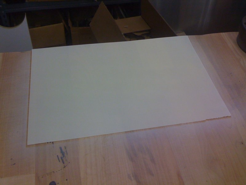
Painted Drafting Paper
51
Discovering paint could be applied to "Clear-Print" drafting paper occurred
totally by happen stance. I knew I was going to have to Hand Letter the scale
onto a surface, but I also knew if I could use an ink pen instead of a paint
brush, the result would be far superior. So I painted a piece of drafting paper
to see what would happen to it. Would it shrivel up? Would the paint puddle,
or make some other undesirable result? Would I even be able to still see through it?
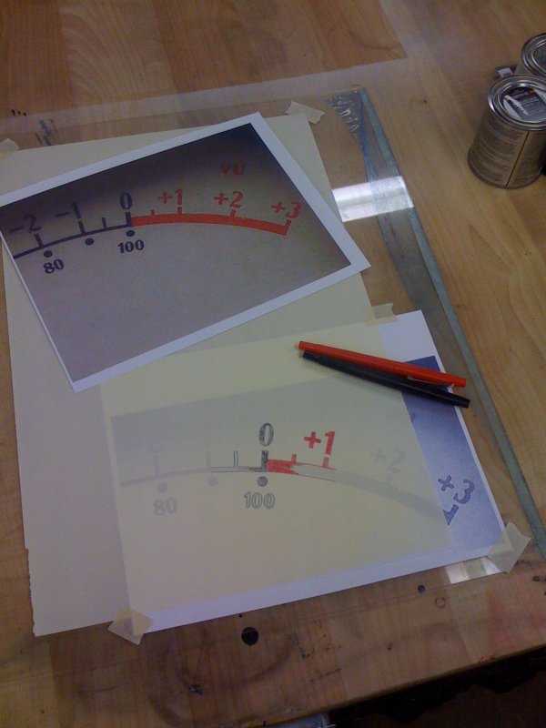
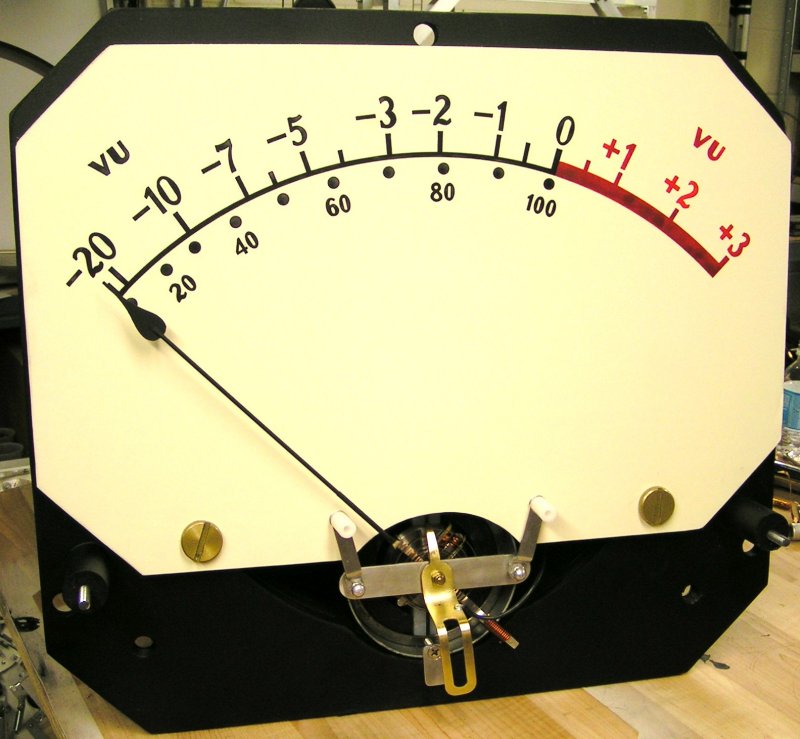
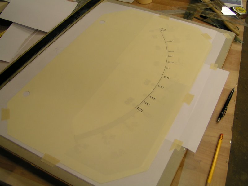
Scale Card
52
Testing hand rendering of the original Weston Font. Here, the type "A" scale has the "20 to +3" in
larger type on the top arc, and the "0 to 100" on the bottom arc in smaller type.
02-MAR-2008
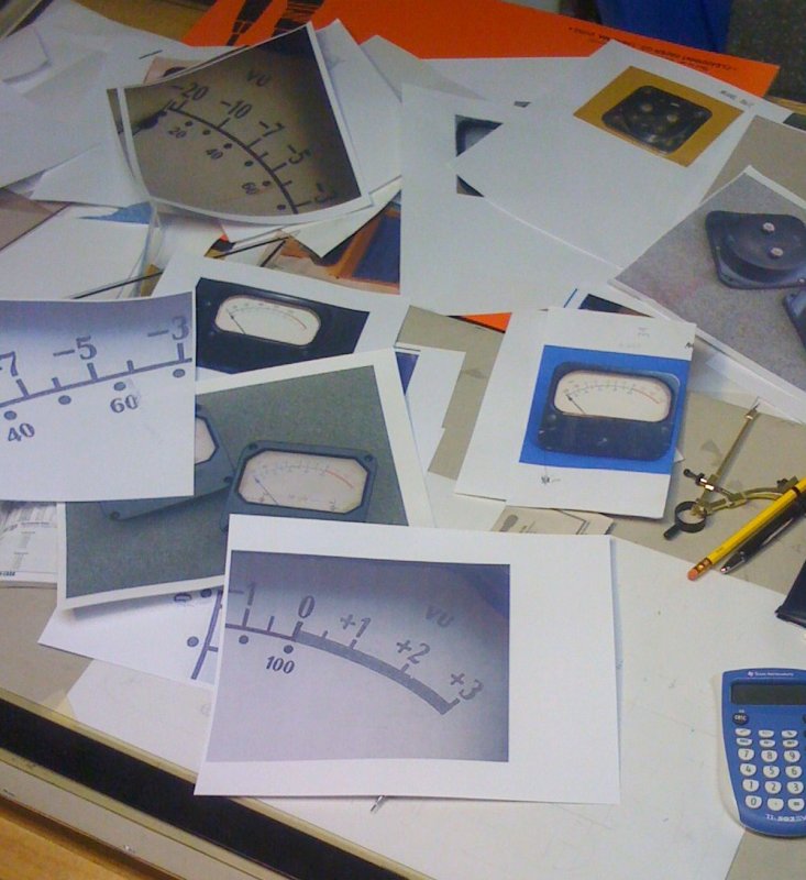
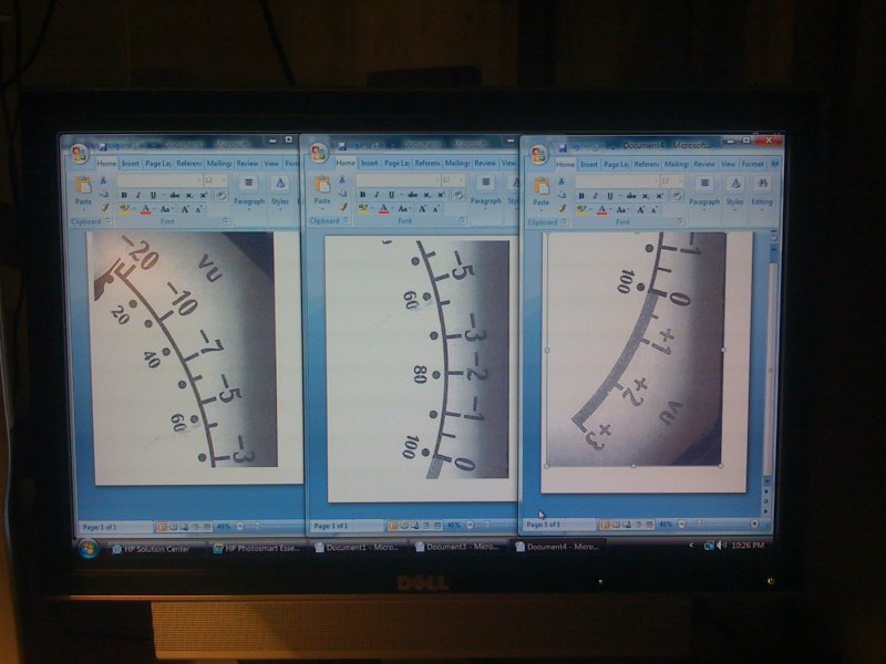
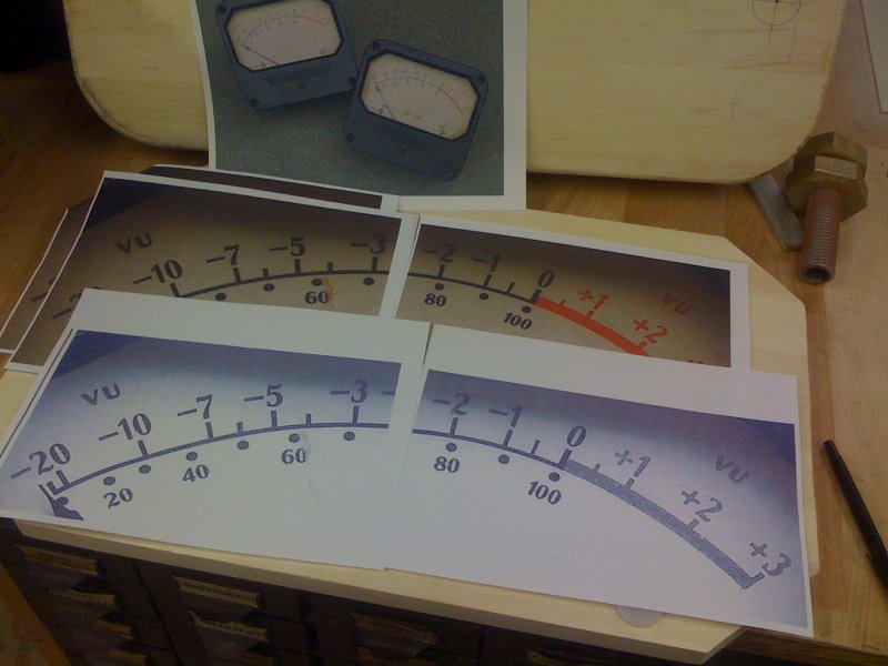
53
Using the computer, I brought up 3 separate Word Document programs. Carefully
scaling, and resizing an inserted photo of the meter scale into each document,
they were then printed onto a standard 8-1/2 by 11 inch piece of paper.
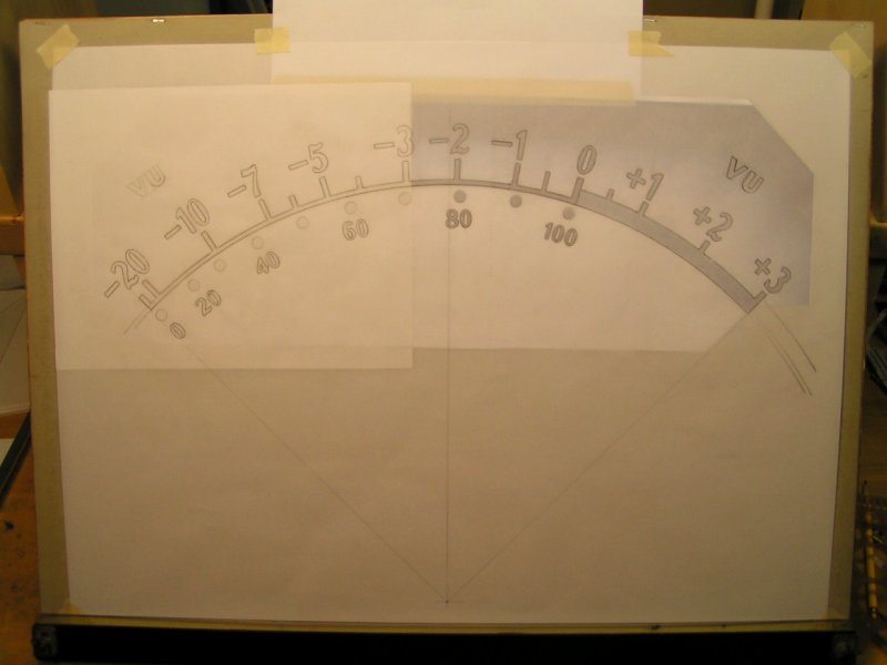
Tracing Meter Scale
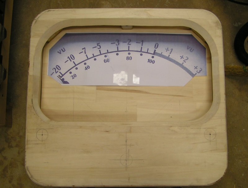
56
Placing drafting paper over the stitched meter scale, it was carefully
traced to alleviate any blemishes, voids, or "drop outs" and to clearly
see where lines of ink would be placed. The tracing sheet also served
as a kind of padding going over the stitched paper seams underneath.
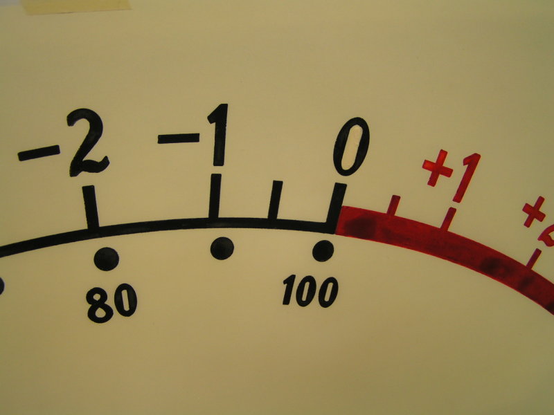
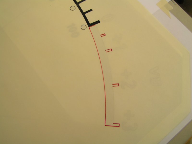
Re-Touching
62
Re-Touching, and Red Ink. The red ink puddles could not be avoided. They happened.
I didn't like the outcome at first, and yet it added to the "retro" effect.
06-MAR-2008
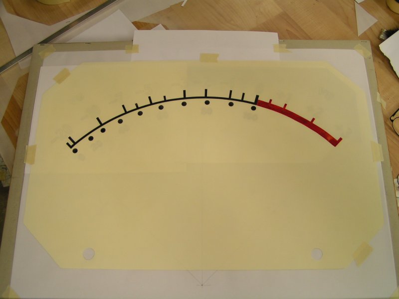
63
Completed [hand rendered] Meter Scale.
Needle Fabrication
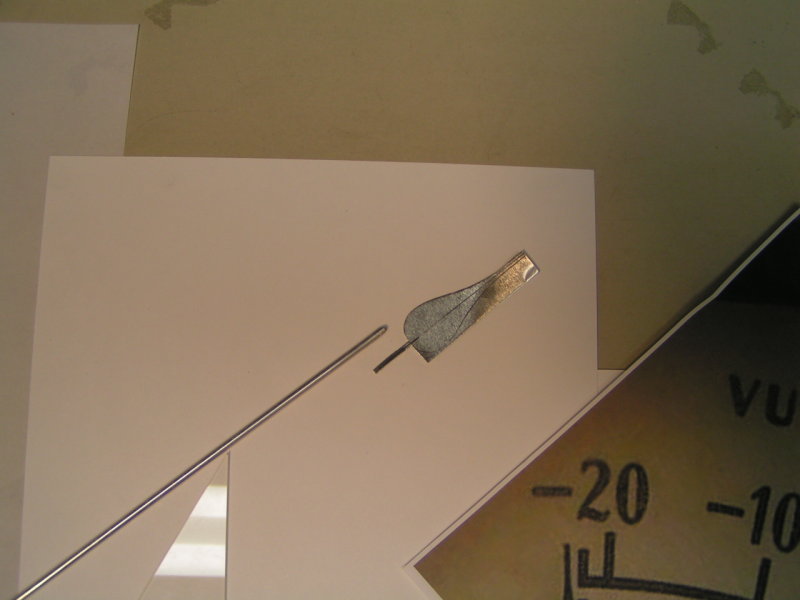
65
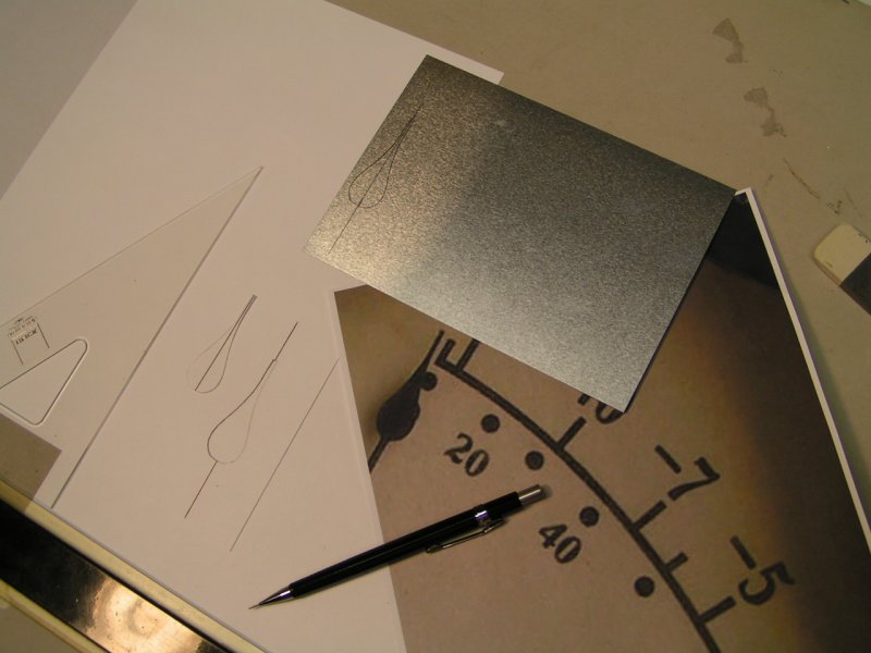
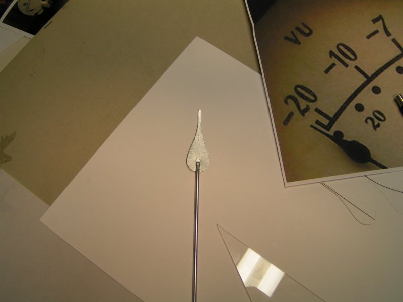
Required shape of needle pointer is cut out from a thin aluminum sheet
leaving a "tail" that can be inserted into the very small diameter
tubing making up the stem portion of the meter indicating needle.
72
"Clear Print" drafting paper attached to removable piece held
in place by two fabricated screws shown unpainted in this photo.
Coil Form
74
Coil form fabricated from scrap piece of acrylic plastic.
First Coil
78
This coil turned out to be "No Good". Somewhere under those many turns of
number 36 AWG magnet wire is a grounded connection to the bobbin rendering
it unusable. The coil was "painted" with two-part epoxy glue while slowly rotated.
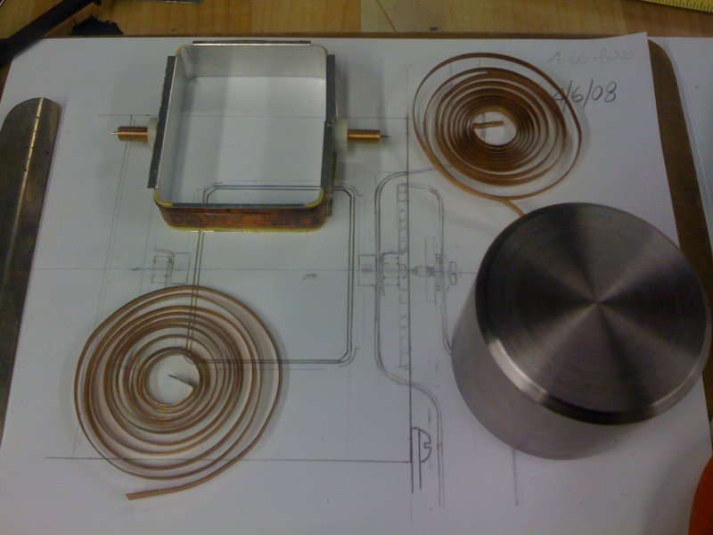
Second "Try"
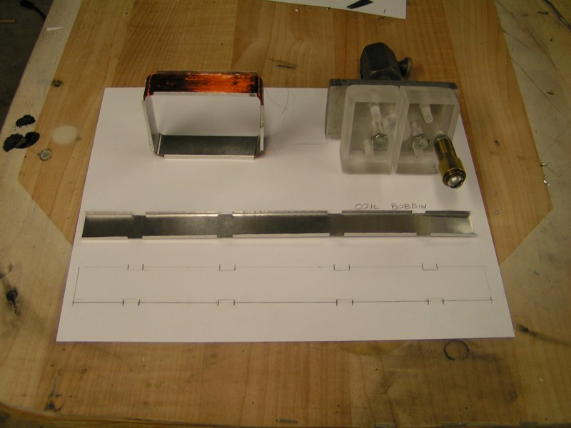
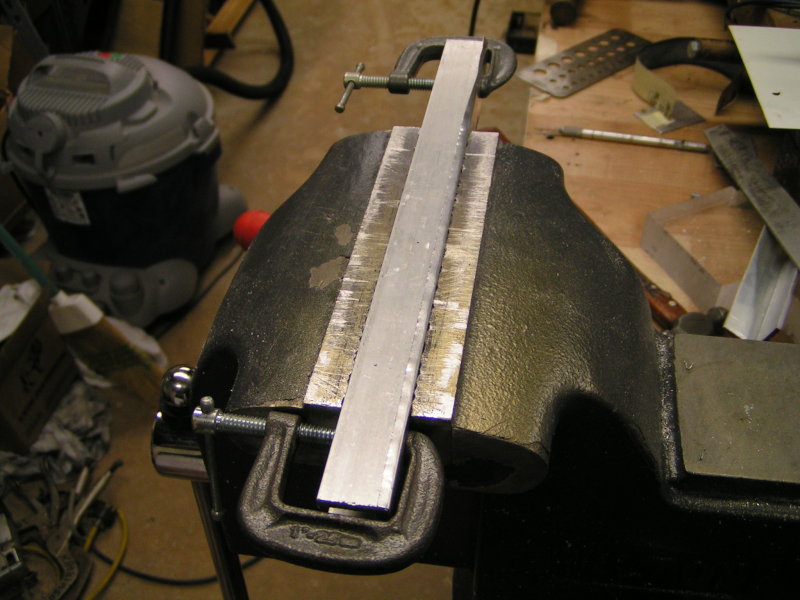
79
First wound coil at upper left, coil winding form at right,
and strip of soft temper aluminum laid out ready to be shaped
around winding form for a second attempt.
06-APR-2008
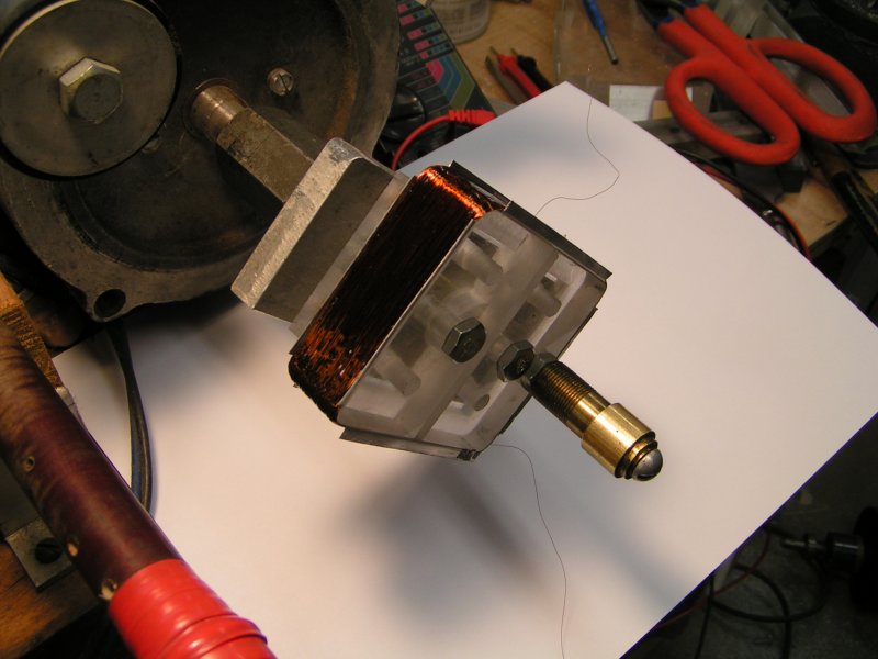
80
View of finished coil. To alleviate potential for the bobbin chafing
the magnet wire, identical rubber bands were placed at each edge.
As the coil was wound slowly around a "zillion" times to achieve
a measured resistance of 600 ohms, it was coated with 2-part epoxy.
Attaching Pivots
81
Each pivot point is a stainless steel sewing needle cut to required length.
The needles were pressed into a drilled hole on the end of threaded 1/4-20
bronze material which was threaded into the white plastic component glued
to the coil assembly. The entire group of glued parts were allowed to fully
cure before being removed from the coil form.
17-MAR-2008
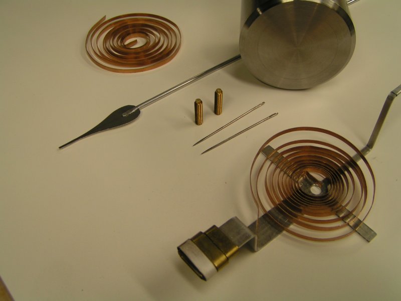
82
The indicating needle in the foreground is from the original meter movement I built
in 2002. The two threaded parts standing upright are the sapphire jewel bearing assemblies.
09-APR-2008
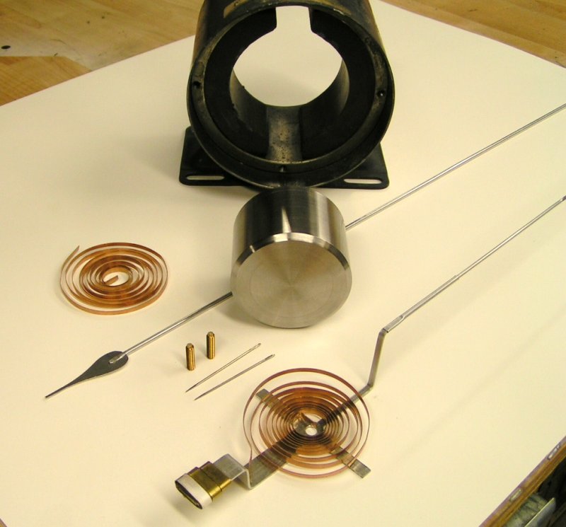
84
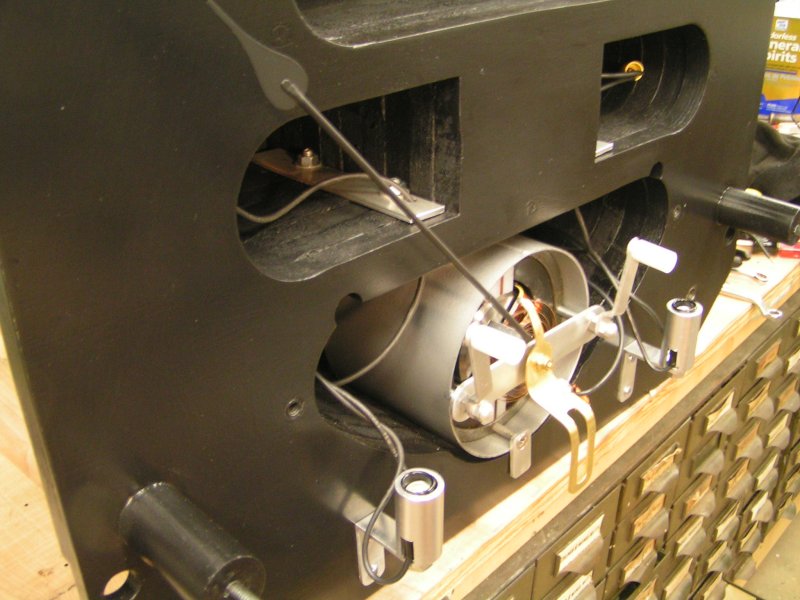
Parts for the meter movement nearly ready for assembling into a working apparatus.
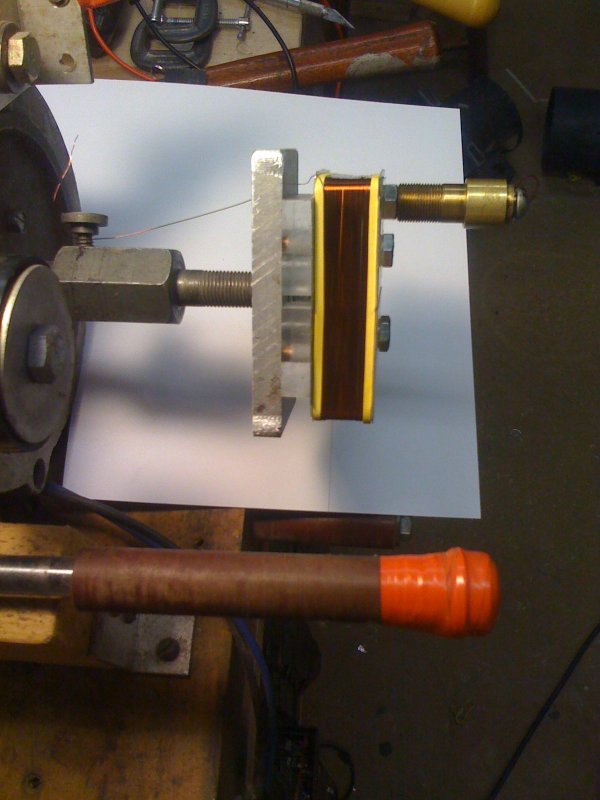
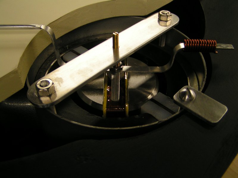
Test Assembly
85
The center "iron", wound coil, indicating needle, and end supports
were carefully assembled together to check clearances, etc.
Balancing Act
86
Notice the Indicating Needle is still bare aluminum color.
Before it was assembled together with mating components
shown here, it was meticulously balanced. The wound piece
of wire at opposite the pointer is a balancing weight.
After the needle was painted black, the mere weight
of the applied paint threw off the balance totally.
It had to be completely rebalanced. In up coming photos
showing the needle painted black, notice the wound piece
of wire is moved back about an 1/8th inch to compensate.
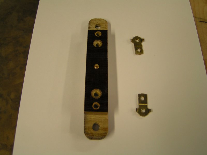
88
Opposite indicator end parts. Sapphire jewel bearing assembly
shown threaded into center of the fabricated phenolic bracket.
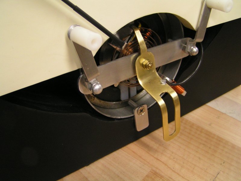
90
This end of the meter movement is adjusted to allow the
indicator Adjustment Bracket to be nearly vertical at
opposite end, positioning the needle as close to
"zero" on the meter scale as possible.
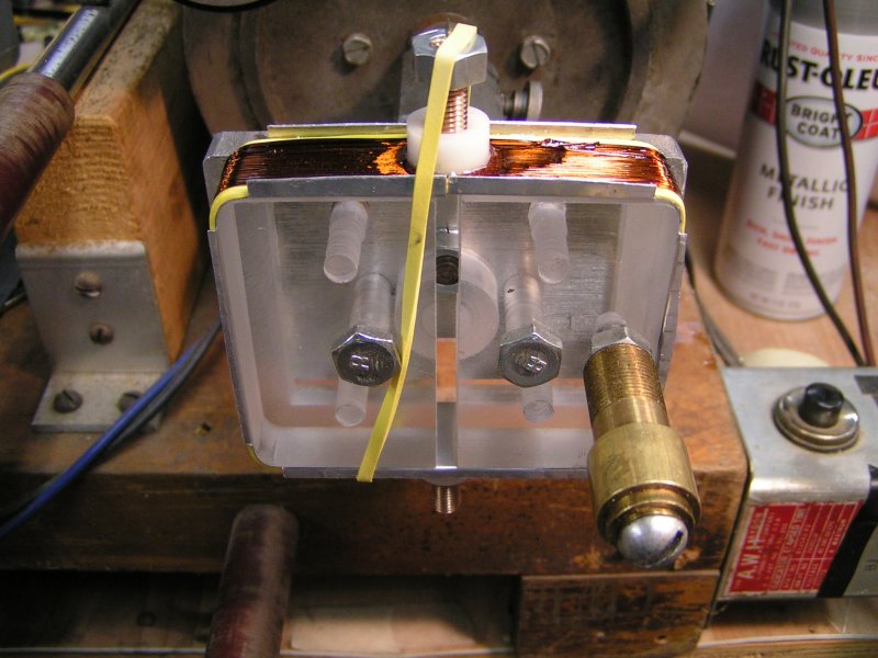
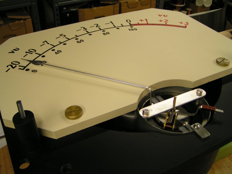
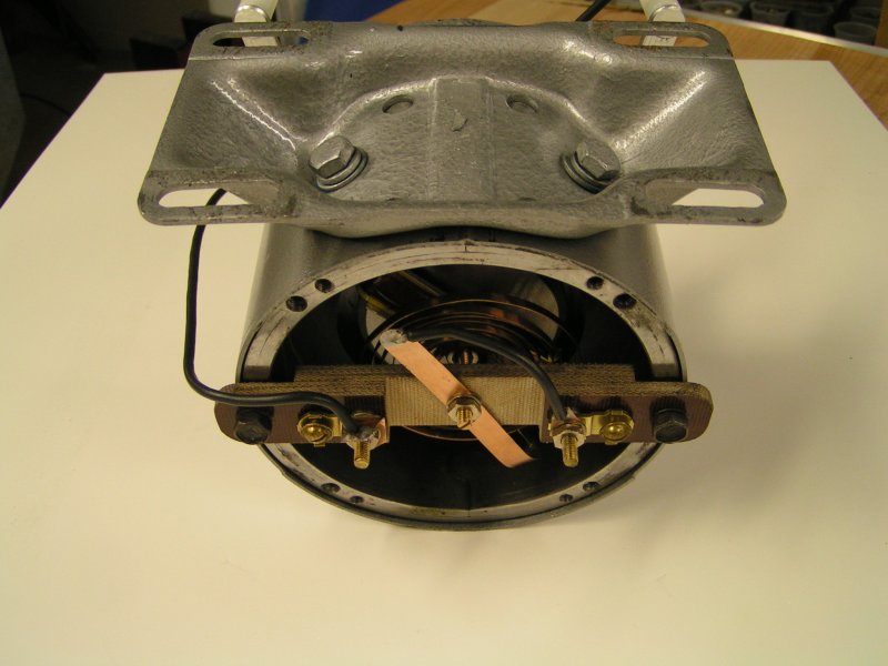
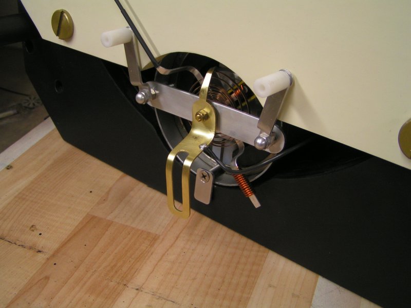
Meter Movement
93
Completely assembled and functioning d'Arsonval Meter Movement.
April 15, 2008
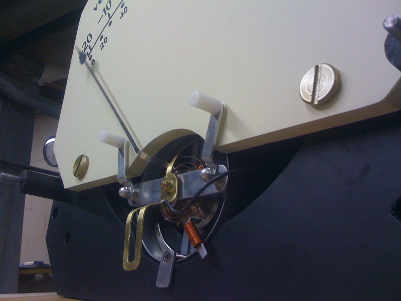
97
Meter face slides behind indicating needle and is fastened
in place with two fabricated Binding Head style screws.
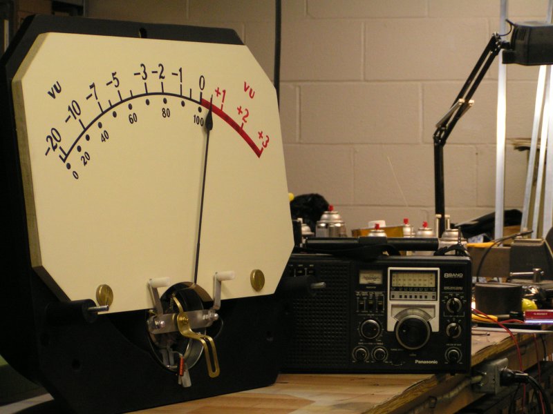
Jammin'
100
Audio from the portable radio is rectified (full bridge rectifier)
driving the needle in rhythm to the music, or "hot air" talk.
"Spoken word" operates the meter more interestingly than music
because of pauses in speech, varying voice intensities etc.
17-APR-2008
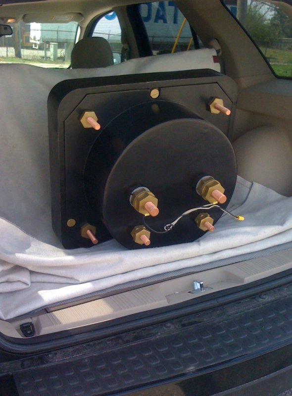
102
On the road to show it off at the North American Model Engineering Exposition (2008)